Pinout
This page provides detailed wiring information for the KRIOS™ MINI electronic speed controller.
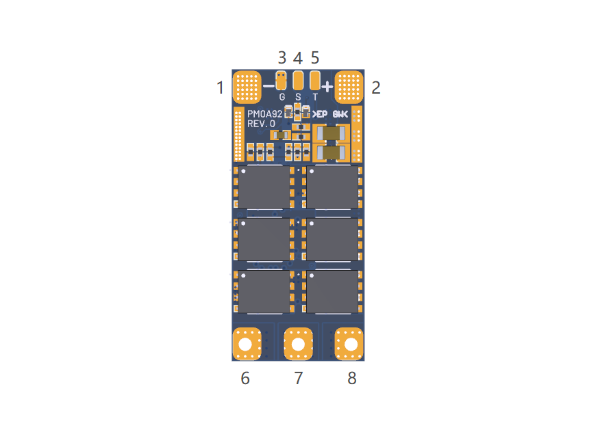
Port Overview
| Port | Description |
|---|---|
| 1 | Main Bus Positive (+) |
| 2 | Main Bus Negative (-) |
| 3 | Ground (GND) |
| 4 | Signal |
| 5 | Telemetry |
| 6 | Phase U |
| 7 | Phase V |
| 8 | Phase W |
Connector Pinouts
info
Models ending with -Z come with twisted-pair 2.54mm connector wires pre-soldered from the factory.
Signal Connector
| Pin | Function | Wire Color |
|---|---|---|
| 1 | Signal | ⚪ White |
| 2 | — | — |
| 3 | Ground (GND) | ⚫ Black |
Absolute Maximum Ratings
| Port/Pin | Parameter | Min | Max | Unit |
|---|---|---|---|---|
| Main Bus | Input Voltage | 12.6 | 30 | V |
| Motor Phase Output | Voltage | V_BUS - 0.6 | V_BUS + 0.6 | V |
| Signal Input | Voltage | 3.3 | 5.0 | V |
| Telemetry Output | Voltage | - | 3.3 | V |
Wiring Guidelines
Power Input
Important
- Ensure input ripple remains less than 5% of the bus voltage
- Maximum recommended input lead length: 30 cm (12 in)
- Use appropriately rated wire gauge for your application's current draw
Signal Wiring
- Connect the signal wire to your flight controller's motor output
- Supported protocols: PWM(50Hz), Dshot, Bi-Directional Dshot, Oneshot, Multishot, Proshot
- Ground wire must be connected for proper signal reference
Motor Connections
| Phase | Description |
|---|---|
| U | Motor Phase U |
| V | Motor Phase V |
| W | Motor Phase W |
note
Motor direction can be reversed by swapping any two phase wires, or via software configuration.