Pinout
This page provides detailed wiring information for the AJAX electronic speed controller.
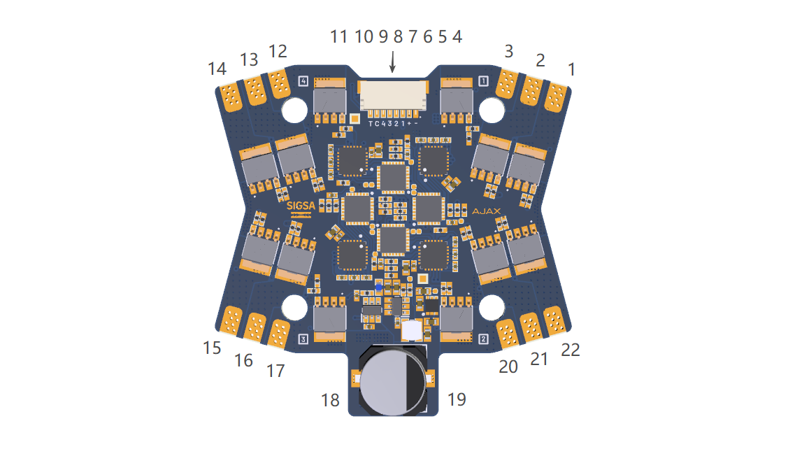
Port Overview
| Port | Description |
|---|---|
| 1 | Motor 1 Phase W |
| 2 | Motor 1 Phase V |
| 3 | Motor 1 Phase U |
| 4 | Ground (GND) |
| 5 | Main Bus Positive (+) |
| 6 | Motor 1 Signal |
| 7 | Motor 2 Signal |
| 8 | Motor 3 Signal |
| 9 | Motor 4 Signal |
| 10 | Current |
| 11 | Telemetry |
| 12 | Motor 2 Phase W |
| 13 | Motor 2 Phase V |
| 14 | Motor 2 Phase U |
| 15 | Motor 3 Phase W |
| 16 | Motor 3 Phase V |
| 17 | Motor 3 Phase U |
| 18 | Main Bus Positive (+) |
| 19 | Main Bus Negative (-) |
| 20 | Motor 4 Phase W |
| 21 | Motor 4 Phase V |
| 22 | Motor 4 Phase U |
Connector Pinouts
Signal Connector
| Pin | Function | Wire Color |
|---|---|---|
| 1 | Ground (GND) | ⚫ Black |
| 2 | Main Bus Positive (+) | 🔴 Red |
| 3 | Motor 1 Signal | ⚪ White |
| 4 | Motor 2 Signal | ⚪ White |
| 5 | Motor 3 Signal | ⚪ White |
| 6 | Motor 4 Signal | ⚪ White |
| 7 | Current | 🔵 Blue |
| 8 | Telemetry | 🟠 Orange |
Absolute Maximum Ratings
| Port/Pin | Parameter | Min | Max | Unit |
|---|---|---|---|---|
| Main Bus | Input Voltage | 12 | 36 | V |
| Motor Phase Output | Voltage | V_BUS - 0.6 | V_BUS + 0.6 | V |
| Signal Input | Voltage | 3.3 | 5.0 | V |
| Telemetry Output | Voltage | - | 3.3 | V |
Wiring Guidelines
Power Input
Important
- Ensure input ripple remains less than 5% of the bus voltage
- Maximum recommended input lead length: 30 cm (12 in)
- Use appropriately rated wire gauge for your application's current draw
Signal Wiring
- Connect the signal wire to your flight controller's motor output
- Supported protocols: PWM(50Hz), Dshot, Bi-Directional Dshot, Oneshot, Multishot, Proshot
- Ground wire must be connected for proper signal reference
Current Sense
The onboard current sense monitor allows the flight controller to read real-time current draw via the Current pin (port 10). To use this feature, configure the flight controller with the following gain value:
- Current Sense Gain: 6.25 mV/A
note
Current sensing requires the flight controller to support analog current input and be configured with the correct gain value. Refer to your flight controller's documentation for setup instructions.
Motor Connections
| Motor | Phase U | Phase V | Phase W |
|---|---|---|---|
| Motor 1 | Port 3 | Port 2 | Port 1 |
| Motor 2 | Port 14 | Port 13 | Port 12 |
| Motor 3 | Port 17 | Port 16 | Port 15 |
| Motor 4 | Port 22 | Port 21 | Port 20 |
note
Motor direction can be reversed by swapping any two phase wires, or via software configuration.